TOC:Unit2 - Finite Automata With Output ( Moore,Mealy Machines)
Finite state machines are composed of a finite number of states. These machines respond to some input by changing from one state to another. This change of state is also called transition.
Moore and Mealy machines are called Finite Automata with output. This is different from a DFA or NFA (Finite Automata without output) where there is no output (input is either accepted or rejected).

Moore Machine
A Moore machine is an FSM (Finite State Machine) whose output depends on the present state. It is defined by 6-tuples (Q, Σ, Δ, δ, λ, q0):
Q = finite set of states
Σ = Input symbol
δ = Transition Function (Q x Σ -> Q)
q0 = Start state
Δ = Output Symbol
λ = Output function (Q -> Δ)
The output of a Moore machine in response to the input string a1 a2 a3 a4 ... aN is λ(q0) λ(q1) λ(q2) … λ(qN) where q0 q1 q2 is the sequence of states such that δ(qi-1, ai) = qi
Example:
Consider the following Moore machine
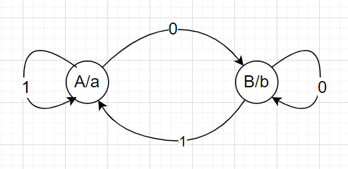
The transition table for the above machine will look like this:
Current State | Next State | Output | |
0 | 1 | ||
A | B | A | a |
B | B | A | b |
The output for the string “1010” in the above machine will be:
States: A -> A -> B -> A -> B
Output: a a b a b
Note that for a string of length N, the output string will have length N+1.
Example :
The below diagram is a Moore machine example.
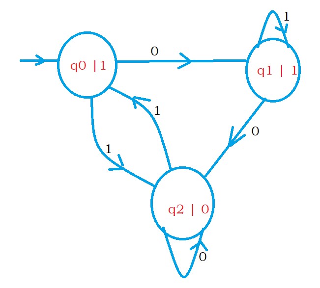
On state q0, we have an output symbol 1.
So, if we are in state q0, this means the machine will display 1.
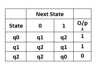
The below diagram shows the transition table for the Moore machine. We have an output mentioned in each state.
Take an input string 01010.
We start from the initial state q0. The machine will display output 1 because we are in state q0.
After taking the first input symbol 0, we move to state q1. so the machine will display 1.
Similarly, after processing the input string 01010, we get the output 111011.
Mealy Machine
In a mealy machine, the output depends on the present state as well as the present input symbol. Here, the output is fixed for every transition (instead of state).
The mealy machine is also defined by 6-tuples (Q, Σ, Δ, δ, λ, q0):
Q = finite set of states
Σ = Input symbol
δ = Transition Function (Q x Σ -> Q)
q0 = Start state
Δ = Output Symbol
λ = Output function (Σ x Q -> Δ)
Example:
Consider the following mealy machine:
The transition table for the above mealy machine will be:
Current State | New State | |||
0 | 1 | |||
State | Output | State | Output | |
A | B | a | A | b |
B | A | b | B | a |
The output for the string “1010” in the above machine will be:
States: A -> A -> B -> B -> A
Output: b a a b
Note that for an input string of length N, the output string will also have length N.
Example :
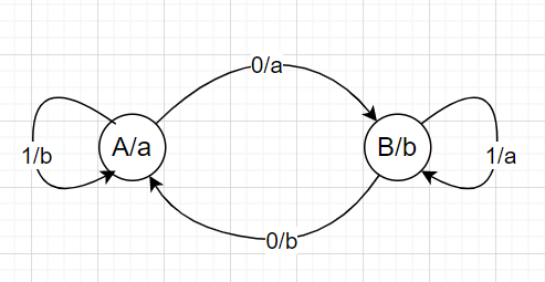
The below diagram shows the simple mealy machine.
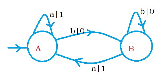
We have two states, A and B.
On state A, if we see the input symbol a, we move to state A and display output 1.
We define output on the transition. Not on the state.
On state A if we see the input symbol b, we move to state B and display output 0.
The below diagram shows the transition table for the mealy machine.
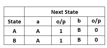
Take an input string abbba.
We start from the initial state A, take the first input symbol 'a', move to state A, and display 1.
Take the next input symbol 'b' and move to state B and display 0.
Similarly, we process the remaining input symbols.
The mealy machine will display the output 10001.
Differences b/w Moore and Mealy machines
| Moore Machine | Mealy Machine |
| The output depends only on the present state. | The output depends both on the present state and the present input. |
| Generally, a Moore machine has more states. | It generally has fewer states than Moore's machine. |
| Less hardware requirement for circuit implementation. | The hardware requirement is comparatively more for circuit implementation. |
| Moore machines react slower to input. | They react faster to input. |
| The output and state of the change of the device are synchronous with the clock edge. | The output generation is asynchronous. |
| These are generally easy to design. | Comparatively difficult to design. |
Similarities b/w Moore and Mealy machines
- Both Moore and Mealy machines do not have any final state.
- They both produce output in the form of string.
Conversion of Moore To Mealy Machine
----------------------------------------------------------------------------------------------------------------------------
The two most common methods for converting Moore to Mealy machine are:
- Converting a Moore Machine to Mealy Machine using transition table
- Converting a Moore Machine to Mealy Machine using transition diagram
Conversion of Moore To Mealy Machine using transition table
Example 1 . Find the Mealy Machine equivalent to the following Moore Machine.
| Present state | Next state | Output | |
| 0 | 1 | ||
| A | A | B | 0 |
| B | B | C | 1 |
| C | C | D | 0 |
| D | D | A | 0 |
Solution :
- Finite set of states = A,B,C,D
- Finite set of Input alphabets = 0,1
- Finite set of output alphabets = 0,1
- Start state = A
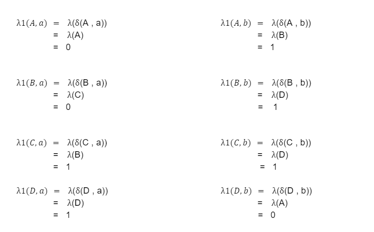
- Find the output function λ1 for all the states and all the input alphabets
Now draw the transition table corresponding to the above output function
| Next state | ||||
| Input = 0 | Input = 1 | |||
| state | output | state | output | |
| A(Inetial state) | D | 0 | B | 1 |
| B | B | 1 | C | 0 |
| C | C | 0 | D | 0 |
| D | D | 0 | A | 0 |
Conversion of Moore To Mealy Machine using transition diagram
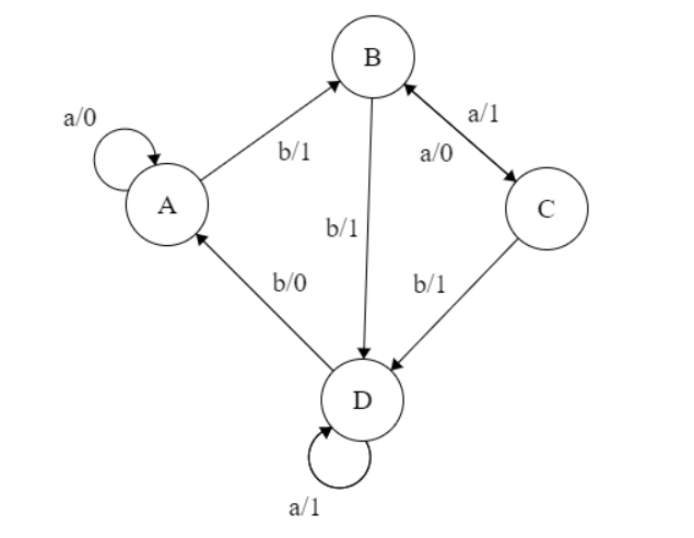
Example 2 : Transition diagram for the Moore Machine is given below.Construct the equivalent transition diagram for the Mealy Machine.
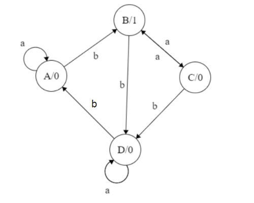
Solution: Transition table corresponding to the above transition diagram:
| Present state | Next state | Output | |
| Input = a | Input = b | ||
| A | A | B | 0 |
| B | C | D | 1 |
| C | B | D | 0 |
| D | D | A | 1 |
- Finite set of states = A,B,C,D
- Finite set of Input alphabets = a,b
- Finite set of output alphabets = 0,1
- Start state = A
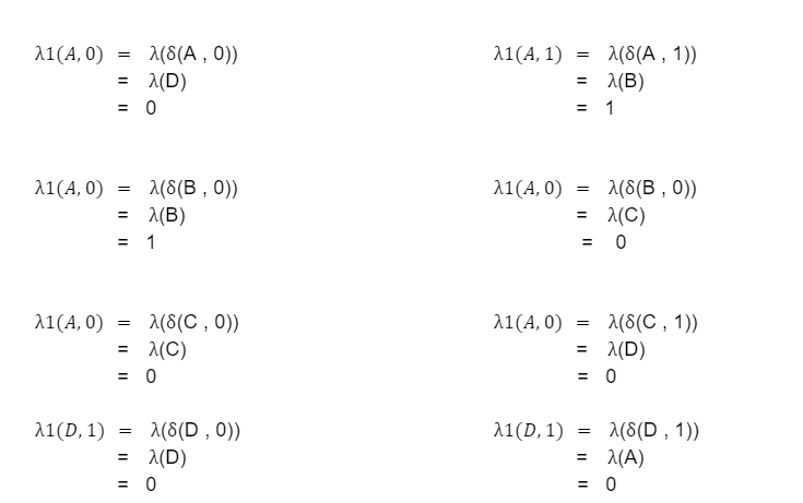
- Output function λ1 is given by
Now , construct the transition table corresponding to the above functions
| Present state | Next state | |||
| Input = a | Output | Input = b | Output | |
| A(Initial state) | A | 0 | B | 1 |
| B | C | 0 | D | 1 |
| C | B | 1 | D | 1 |
| D | B | 1 | A | 0 |
The equivalent transition diagram can be drawn as follows:
It is the required transition diagram for the Mealy Machine. so we have to explore a variety of examples for Conversion of Moore To Mealy Machine.
Note: It is clear from the above process that only the output function λ1 is different. All other tuples are the same for both the machines.
Steps for Conversion of Moore To Mealy Machine
Let M1 = {Q,Δ,δ,λ,A} be a Moore Machine, then to construct the equivalent Mealy Machine M2 = {Q1,Δ1,δ1,λ1,A1} proceed as follow:
- Finite set of states for equivalent mealy machine = finite set of states of given Moore machine i.e Q1=Q
- Finite set of input alphabets for resultant mealy machine = finite set of input alphabets given Moore machine i.e Σ = Σ1
- Finite set of output alphabets for resultant Mealy-Machine = Finite set of output alphabets of given Moore machine.
- The output function λ1 is a function of the present state and input symbol
- I.e λ1(Q, A) = (δ(Q , A)) for all states q belongs to Q and input symbol A belongs to Σ
- Start state for the resultant mealy machine = start state of the given Moore machine
Note: It is clear from the above process that only the output function λ1 is different. All other tuples are the same for both the machines.
Conversion of Mealy Machine to Moore Machine using Transition table
Steps
- In this conversion process we split a state q of the Mealy machine with several states, the number of such states is equal to the number of different outputs associated with state q.
- After adding extra states, when we find output associated with state q is the same everywhere in the table, we add the output as the output of the state q (i.e In the Moore machine output depends only on the present state).
- After splitting the columns, we get an equivalent Moore Machine.
Consider the below transition table of a Mealy machine whose transition diagram is given above:
Input=0 Input=1
| Present State | Next state | Output | Next State | Output |
q0 | q2 | b | q1 | b |
q1 | q3 | b | q2 | b |
q2 | q2 | b | q2 | b |
q3 | q2 | b | q0 | a |
For state q0, we can find only a is associated-output with state q0 in the 4th row.
So, q0 → a
for, state q1, we can find only b associated output with state q1 in the 1st row. So, q1 → b
Similarly, we can find
q2 → b
q3 → b
So, the transition table of the corresponding Moore Machine
| Present State | Input 0 | Input 1 | Output |
q0 | q2 | q1 | a |
q1 | q3 | q2 | b |
q2 | q2 | q2 | b |
q3 | q2 | q0 | b |
Example :
The below diagram shows the mealy machine.
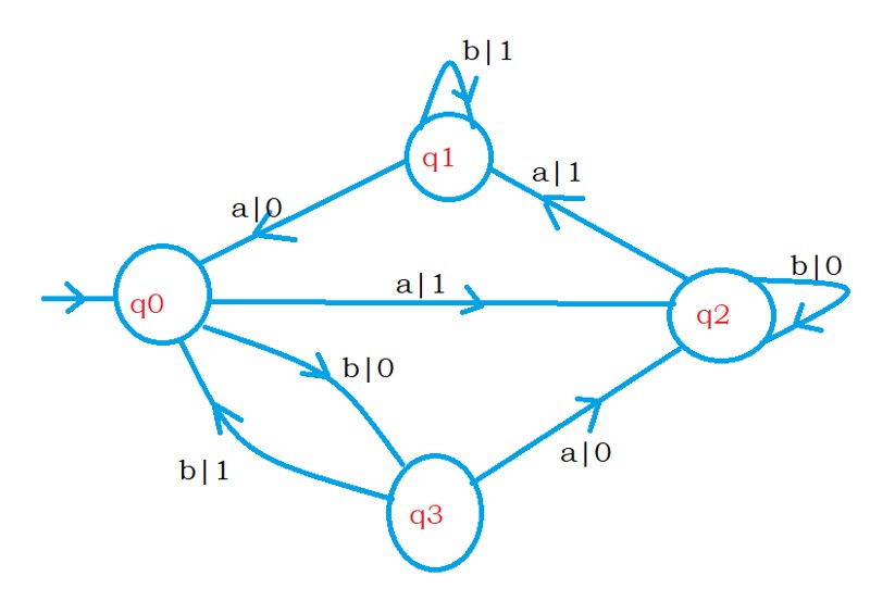
The mealy machine will display output based on transition.
Procedure:
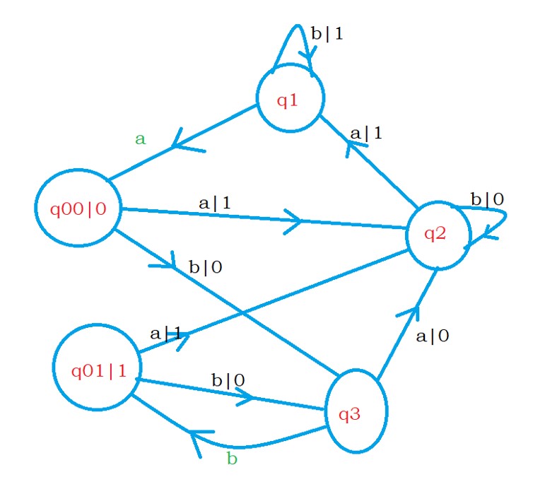
Start from the initial state , q0 .
The initial state q0 has two incoming edges.
One incoming edge is from state q3 and the other from state q1.
The output on the two incoming edges is 0 and 1.
So we take two different states in the Moore machine.
One state is going to display 0, and the other state display 1.
One state is named q00, and this state display 0.
another state is named q01, and this state display 1.
on state q1, if we take input symbol a, we move to state q0 and display 0.
Similarly, on state q3, if we take input symbol b, we move to state q01. To display 1.
We write the outgoing edges in the mealy machine on both the states in the Moore machine.
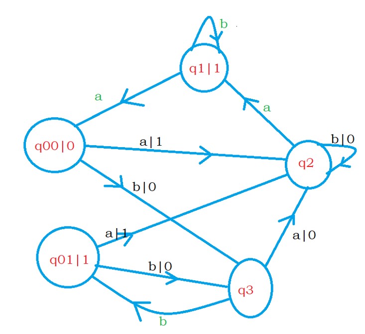
On state q0, we have two outgoing edges. We mention both edges on the states q00 and q01 in the Moore machine.
The below diagram shows the Moore machine after converting state q0.
Similarly, convert all the states.
Now we will consider state q1.
We have two incoming edges on state q1.
Both incoming edges display output 1, so we take one state q1 and display output 1.
Write the incoming and outgoing edges for state q1.
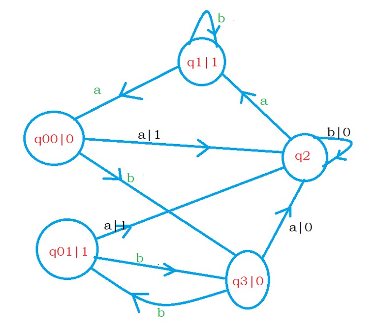
The below diagram shows the Moore machine after changing state q1.
Now we consider state q3.
We have two incoming edges on state q3.
Both the incoming edges display output zero.
We take only one state, q3, and the state will display output zero.
We write incoming and outgoing edges to state q3.
The below diagram shows the Moore machine after converting state q3
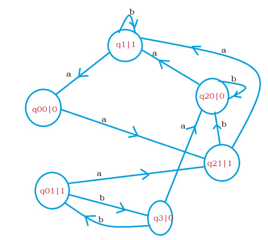
Now we consider state q2.
We have four incoming edges to state q2.
Two incoming edges are displaying output 1.
Two incoming edges are displaying output 0.
We take two different states q20 and q21.
The state q20 will display output zero. And the state q21 will display output 1.
We write the incoming and outgoing edges to states q20 and q21.
The incoming edges which are displaying one will move to state q21.


Comments
Post a Comment